Yes, thats right! I will show you how to build a fully functional night vision device!
Press read more for the whole How-to!
At first you will need an old analog camcorder.
I bought 3 of them for 10 € on ebay. They are very cheap and full of useful electronics.
The part we’re interested in is the viewfinder on top of the camcorder. Carefully disassemble the camcorder and remove the viewfinder.
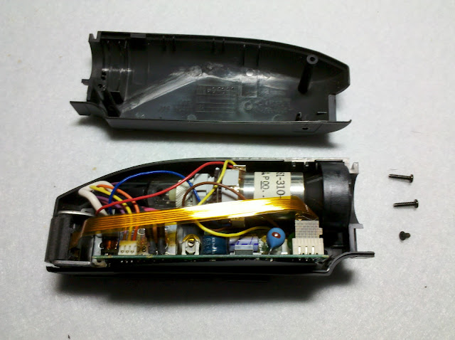
Remove the lense part on top of the viewfinder and carefully open the casing.
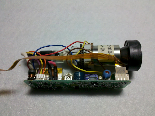
As you can see there is a thin flexible cable coming from the circuit board. No matter what kind of viewfinder you have, there should be a similar cable.
Now we have to identify the connections for power and the connections for our video signal ( I’ll explain the video signal part later ).
You can see the connections in the top right of the circuit board. I carefully tested which ones were power (5volts). After that i soldered some wires to the pins.
This picture shows me trying to find the video signal input pins. After discovering the power pins i just turned it on, took a video signal and tried the remaining pins until something showed up on the small screen.
The next step is putting the viewfinger back together.
In order to see something in the dark we will need a CMOS camera.
There are plenty of CMOS cameras out there. I purchased one with little IR leds. CMOS cameras can detect IR light and thus are with the help of IR leds able to see in the dark!
This camera was 11$ in a world wide shipping shop named dealextreme. It works perfectly!
It runs on 9 Volts and has an analog video output. I cut of the plugs and wired the video output directly to the viewfinder. The yellow cable is the video signal, the white is audio and the black is power.
Now its time for a test of our little set up. Camera and viewfinder are running…
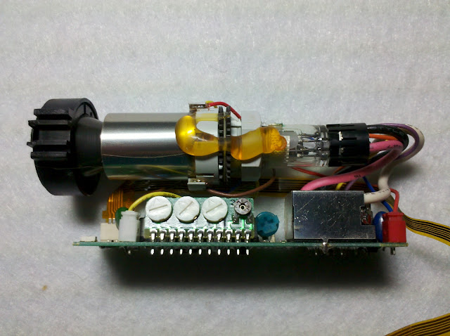
… and it works! Now its time to calibrate the viewfinder. There are little variable resistors on the back of the viewfinder which can be use to in and decrease brightness and contrast:
All you need to do now is find a nice casing, take the camera and viewfinder and some batteries and your night vision device is finished!
If you want to see even more in the darkness, you can add some IR leds. They are cheap and easy to install. This is my night vision device. You can see everything up to 20 meters in a completely dark knight. I added some switches to turn on/off the camera, the viewfinder and the additional IR leds. I even added a little video socket so I’d be able to record the footage from the camera at night if i wanted to.
And here are some videos, I am sorry for the poor quality, but due to the viewfinders frequenzy it was very difficult to film the scene. The video was shot in complete darkness.
Here’s a picture of the infrared Leds turned on and off.
Here’s a picture of the infrared Leds turned on and off.
http://www.doityourselfgadgets.com


The viewfinder seems identical to the one mounted on my Sony CCD-V800E, so I'm pretty positive this mod can be replicated on that camera.
Anyway, congratulations for being featured on Hack a Day!
It looks so simple but I have problems with the most important part. I can't find th power input pins without damaging the viewfinder (I've already killed one). Can you suggest me what voltage should I use?
If your camcorder can be powered on, I suggest carefully probing each lead to the display with a multimeter. Watch out for HV!
I used this method to work out the pinouts and operating voltage for mine. I was lucky enough to find one that runs on only 5VDC.
I don't have the camera part, just the camcorder, so I should find another way 🙁 Thank you for idea!
I used 5 Volts! Don't touch the tube when it is turned on due to HV!
There should be a relatively large capacitor on it, probably rated at 6.3 volts. The power input pins will be connected directly to this capacitor. Most of them operate at 5V DC. Then just guess and check for the signal pin.
I checked and he's right! Thank you for the tip! Look for the capacitor!
I have succesfully powered up the viewfinder. Thank you for all!
Awesome modification. I might have to borrow a friend's electrical equipment and do this! 😛
Where do you buy these cameras? I have looked all over, but all i can find is newer cameras, and the batteries that go to the older ones.
Is there a way to put a zoom on this?
Yes, Just buy a CMOS camera which has a zoom on it. There are pretty cheap ones with 5x zoom…
http://www.dealextreme.com/p/ntsc-mini-surveillance-av-camera-628x582px-6019?item=30
……………. or just keep the camera intact & add infrared LEDs via the hotshoe? That way you get a rechargeable device & monster zoom facilities.
this is awesome, i was trying to build one from scrap and had so many problems, thanks for the steps on how to do this it helped a ton! youre awesome and i look forward to more
Hello!
Really liking this idea and Im going to make a try at building one. Im confused though. How do I power both the view finder and the camera? Do they need separate battery supply i.e 5v and 9v?
Any help would be great! Excited to start building it!
Thanks
F
I noticed you are using four AA batteries, am I correct to assume that the four AAs are used to power up the CRT?
Would this not result in a combined output of 6v? I'm new to many electronic concepts, but is the 6.3v capacitor working as a surge protector in this instance?
Will this shorten the life of the circuit?
Actually, there was a pretty good question here; why not just add IR LEDS to a working camera? What does the CMOS camera do that a fully working camcorder can't do? Otherwise, neat hack and I learned a few things. Thanks!
Would it be possible to buy or rig a CMOS to have a targeting reticule or crosshair in the image projected through the view finder?
Careful this night vision can be defeated with a strong visible light source. Erny used this stuff to sneak up on deadman but dm pulled out a really bright flashlight and defeated the night vision and blinded erny. Then he took the chance to soil the young lads pants. Do not stare into the sun with these on, momma was wrong, that is not where the fun is. I would suggest avoiding this and simply buying $8000 generation 3 because I am a gear snob. I have billions in bullion, chicken specifically…
Camera has to be 380TVL or it doesnt matter? I found this camera on ebay and I'm curious if could be compatible with viewfinder. http://www.ebay.com/itm/170854112996?ssPageName=STRK:MEWAX:IT&_trksid=p3984.m1423.l2649
Hallo! Thank you for your comment!
Yes, this camera should work fine! Connect the two cables from the video signal to the right cables on the viewfinder!
i'm thinking of making this type of nv setup, but finding an old analog camera viewfinder is proving rather difficult, i then came to the idea of using some itheater type video glasses with av input from the CMOS camera, also allowing handsfree capability. Some cheap variants of these glasses can be found on ebay for around $100. Has anyone tried this?
I cannot find any old camcorders on ebay or any other website. Do you have any suggestions on where I can find one like the one you used for this?
Hello, I search in ebay this camera, I don't find it, can you help me ?
nice build!
I imagine that you could just use a 9v supply and then a 5v regulator to make your 5 volts. Just make sure the regulator is able to handle the current it needs.
If it isn't a CMOS camera, the IR LEDs won't really do much for nightvision. Turn off the lights and have someone point a remote at you and press buttons on it while you try to walk around. Now try it while using a cell phone camera. It's the same effect of comparing an old style camcorder to a CMOS camera. And for those that don't know, you can use a cell phone camera to see if an IR remote is working. I imagine the point of it is to make a smaller nightvision camera for less.
All camcorders have an IR filter over their image sensor, so adding IR LEDs as illumination won't help. You'd need to take the thing apart and remove the tiny glass filter from the CCD imager, and this is not very easy to do in most cases.
The exception would be if you have a camcorder that had "night vision" capabilities like the Sony Nightshot. These cameras have a switch that removes the IR filter when you put it in nightshot mode, and they work great with an external IR light source.
Most CMOS and CCD security cameras are made without IR filters, specifically so they work in low-light conditions. This is why the author recommends using one of those for this project.
i wonder if others could do this with an iphone……
hi, well done on this project, im hoping to make something similar,
tell me how did you sort out the two different power supplies ? the viewfinder was 5V and the camera was 9V, what do i need to reduce the power for the viewfinder ?
I used a 9V battery and a some little resistors for the viewfinder. You could also use a 7805 voltage regulator. hook it up to 9V and its output is 5 volts!
thanks for that. instead of using a salvaged crt from a viewfinder i was thinking of using a tft lcd display, their really cheap on ebay but was wondering if i could hook a camera directly to it or would i need some additionl software ? none of the suppliers seem to have a answer for me 🙁
If you can feed a DC Video Signal ( Analog AV Signal ) to the screen, it should not be a problem. Take a look at my remote controlled water gun, I used a mini lcd screen and a camera (which happens to be IR sensible, too).
I really want to make this but I am having trouble finding a old analog camcorder. I would like one like your Panasonic MC 10 but I can't find those. What did you search to find the MC 10, if you don't know, will this work?http://www.ebay.com/itm/Vintage-1980s-RCA-CPR-300-VHS-VIDEO-CAMCORDER-w-Accessories-Case-80s-party-/140964612084?pt=Camcorders_Professional_Video_Cameras&hash=item20d22547f4
Yes the viewfinder looks good!Good luck with carfully identifying the right cables!
Thanks I was going for something that won't take alot out of my pocket so how about this camcorder? http://www.ebay.com/itm/JVC-Compact-VHS-Camcorder-GR-AX700-/380631197069?pt=Camcorders_Professional_Video_Cameras&hash=item589f63258d#ht_807wt_1170
Sorry to bother you again, but how about this one, I have been browsing ebay for an hour and this is the cheapest one I found. http://www.ebay.com/itm/JVC-GR-GR-SXM240-Camcorder-Black-/251268309042?pt=Camcorders_Professional_Video_Cameras&hash=item3a80c22032#ht_246wt_932
They both look good and I think they should work! I also looked for cheap analog camcorders, I once bought a package of 5 broken ones for 10$ – best deal ever!
Thanks alot! I have a question. I looked at the camera on DealExtreme and the camera has a red port for power, but then why did you cut the wire instead of just plugging the power source into the port?
Thank you so much, built all of it, every single thing, except the C36 coil gun… I failed on that, and couldn't finish it, so it was a waste, could I possibly BUY one from you?
Is there a way I can contact you for a step by step guide or something?
wait? the view finder have CRT screen inside?
Yes 🙂
Nice post. I used to be checking continuously this weblog and I am inspired!
Very useful info particularly the ultimate phase
🙂 I deal with such info much. I was looking for
this particular information for a long time. Thank you and good luck.
Have a look at my blog … xerox 8560 specs
hey you might want to add that the wave lengths of infrared over 750mm are invisible less than that and it wont be so stealthy anymore
you can make a filter for visible light using, if I remember correctly, exposed film, for a camera
Hi, this is a good project. Can you tell me how to connect video input and output? I ask this because when I examine a camera / monitor I have to connect the video output / input to input / output and GND. Thanks
need a little help here with the singal leads 😛
ive got yellow and orange but when I hook them up to the brown en yellow leads on the viewfinder not a thing happend… any suggestions or anything?
Thanks for this. Can I modify a web can (remove ir filter and block visible with film negative) then connect the video output from cam to video input on view finder?
Obviously id pinout properly positive and negative of cam and CRT screen to power and the web can video line out to CRT line in…that makes sense right?
Thanks
As already was told you need a ANALOG video output. An ordinary Webcam has a digital one.
But in generaly you can connect any "cam" to any "screen" you just need to modify the video Signal and therefore you need an aditional converter (selfmade or bought). But its to complicated for such a project.
BTW:Nice guide. Could have some more theorie and details but still very nice. If i have more time i build something similar.
i'm really interested in making this but i'm having trouble finding a suitable camera, can someone please point me in the right direction. im in the UK
I'm in the process of making this but have run into a bit of a snag. I have both the CMOS camera and the CRT viewfinder hooked up to separate 9v sources that are run through 5v regulators. Everything works fine, I even found the correct pins on the viewfinder circuit. However, the crt only shows an image when the additional video output jack is hooked up to a tv. The image will not show on the viewfinder otherwise. I'm rather new to this, but my theory is that in order to work the signal has to be a certain voltage and the extra draw from the TV pulls it down to the magic number. If this is the case can I simply put a resistor or series of resistors into the circuit to solve my issue? I hope this thread is still alive!
Quick follow up, when there is no tv connected the signal lead is sending 2.0v to the crt. When it IS connected there is a solid .70v and the viewfinder has picture. This is why I thought I needed a resistor or something that will drop the signal voltage to .7.
http://imgur.com/VWOE5rN My version, the route of the video signal marked with red.
You have to connect the camera's and the viewfinder's ground together. Physically there are only 3 wires coming from the camera "+" "-" and video signal. You have to make a circuit otherwise nothing'll happen. The cameras power connector's and the rca connector's ground/negative outer metal cricle are the same, all connected together.
Are you using a voltage regulator? 7805? What drops it from 9v to 5,7v? I'm using a 7805 voltage regulator. It only has 3 connections, not 4 like your diagram.
The LM2596 is an adjustable step-down voltage converter IC. Rated to 3A.
Specifications: http://www.ti.com/lit/ds/symlink/lm2596.pdf
It requires a series of resistors, diodes and capacitors for correct operation which depend on the input and the prefered output voltage. However I prefer to use the LM2596S circuit which is a prebuilt board with an adjustable resistor, so I can set the output voltage anytime.
I bought them from him(free shipping FTW):
http://www.ebay.com/itm/2pcs-DC-DC-3A-Buck-Converter-Adjustable-Step-Down-Power-Supply-Module-LM2596S-/200964337125?pt=LH_DefaultDomain_0&hash=item2eca686de5
But some cheaper deals've appeared since. Sadly 2$ of shipping costs.
http://www.ebay.com/itm/5X-LM2596s-DC-DC-Buck-Converter-Power-Supply-Step-Down-Module-Voltage-Regulator-/121481989172?pt=LH_DefaultDomain_2&hash=item1c48e40c34
Great setup. I might try this in reducing my screen size. This is my current build http://iboughtthisonline.blogspot.co.uk/2014/12/diy-night-vision.html